
-


-
產品搜尋
首頁 > 宜大-RF高頻洩波微波-同軸電纜及接頭 > YMHD-Ultra Low Loss Microwave RF Coaxial Cable 超低損耗高射頻同軸電纜 > YMHD-Low Loss PTFE Microwave Coaxial Cable & Assembly for up to 26.5 GHz低損耗射頻微波(26.5G)同軸電纜及SMA組裝
.jpg "YMHD-MUA210SD ( UFA210A Type ) RF Low Loss Microwave Coaxial Cable 鐵氟龍耐高溫(雙層鍍銀屏蔽隔離)低損耗射頻微波(26.5G)同軸電纜")


YMHD-MUA210SD

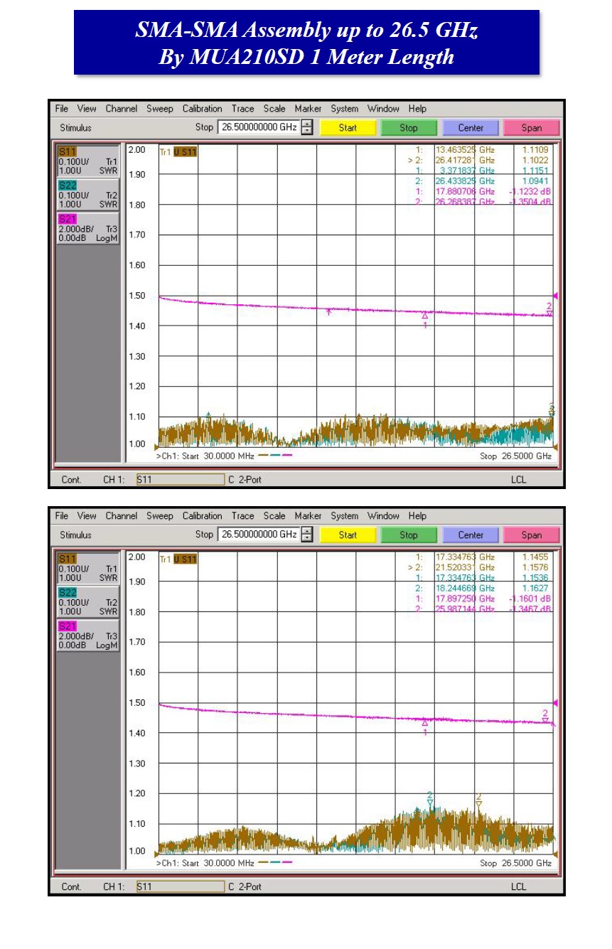
YMHD-MUA210SD ( UFA210A Type ) RF Low Loss Microwave Coaxial Cable 鐵氟龍耐高溫(雙層鍍銀屏蔽隔離)低損耗射頻微波(26.5G)同軸電纜CENTER CONDUCTOR
The center conductor is one of Solid Silver Plated Copper Wire or Stranded Silver Plated Copper Wire in accordance with ASTM B-298. The solid center conductor has a less RF resistance, a lower attenuation, and is more amplitude stable with flexure. The stranded center conductor is excellent in flexibility and is more phase stable with flexure.
DIELECTRIC
The Dielectric is composed by Low density Extrusion PTFE with a lower dielectric constant compared with Solid PTFE. Almost of transmission losses are determined by the dielectric material and structure. In addition, the dielectric material and structure determines the velocity of propagation, the using temperature range, the power rating, the phase and amplitude stability, and a flexibility of cable. The LLC-M series cables are constructed by Low Density Extrusion PTFE having low thermal coefficient of expansion, also based on stable and equal pore distribution.
INNER SHIELD
The Inner Shield is composed by Silver Plated Copper Strip wrapped helically between layers. This shield structure provide the outstanding flexibility with providing 100 % coverage rate. The uniform impedance and ideal contact between individual layers of the shield are achieved by unique structure of Silver Plated Copper Strip wrapping.
OUTER SHIELD
The Silver Plated Copper Wire in accordance of ASTM B-298 is braided tightly over the inner shield. The braiding structure provide the tightness of inner shield and also present the additional shield effectiveness.
OUTER JACKET
The FEP ( Fluorinated Ethylene Propylene ) as the material of outer jacket have the strong resistance to Temperature and Chemical.
MECHANICAL CHARACTERISTICS ( LOW LOSS CABLE ) Low Loss Cable Part No. LLC-MUA147SDLLC-MUA147STLLC-MUA210SDLLC-MUA210STReplacement forUFA147A of Micro-CoaxUFA147B of Micro-CoaxUFA210A of Micro-CoaxUFA210B of Micro-CoaxCenter ConductorSilver Plated Copper WireSolid
0.0359 inch ( 0.91mm )19 Stranded
0.0376 inch ( 0.96mmSolid
0.0551 inch ( 1.40mm )19 Stranded
0.0565 inch ( 1.44mm )DielectricLow Density PTFE0.106 inch ( 2.69mm0.106 inch ( 2.69mm )0.160 inch ( 4.06mm )0.160 inch ( 4.06mm )Inner ShieldSilver Plated Copper Strip0.112 inch ( 2.85mm )0.112 inch ( 2.85mm )0.166 inch ( 4.22mm)0.166 inch ( 4.22mm )Outer ShieldRound Silver Plated Copper Wire0.129 inch ( 3.28mm0.129 inch ( 3.28mm )0.186 inch ( 4.72mm )0.186 inch ( 4.72mm )JacketFEP
( Fluorinated Ethylene Propylene )0.147inch ± 0.005 inch
( 3.73mm ± 0.13mm0.147inch ± 0.005 inch
( 3.73mm ± 0.13mm )0.210inch ± 0.005 inch
( 5.33mm ± 0.13mm )0.210inch ± 0.005 inch
( 5.33mm ± 0.13mm )Jacket Wall Thickness> 0.009 inch ( > 0.23mm )> 0.009 inch ( > 0.23mm )> 0.010 inch ( > 0.25mm )> 0.010 inch ( > 0.25mm )WeightGrams/ft ( Grams / Meter )11g/ft (36.1g/m)11g/ft (36.1g/m)20g/ft (65.6g/m)20g/ft (65.6g/m)Minimum Bend Radiusinch ( mm0.25inch (6.35mm)0.25inch (6.35mm)0.38inch (9.65mm)0.38inch (9.65mm)Flexures10,000100,00010,000100,000ELECTRICAL CHARACTERISTICS ImpedanceOhms50 Ohms50 Ohms50 Ohms50 OhmsFrequency RangeGHzDC-40 GHzDC-26.5 GHzDC-26.5 GHzDC-26.5 GHzVelocity of Propagation%77%77%77%77%Capacitancepf/ft ( pf/m26.2pf/ft (86.0pf/m)26.2pf/ft (86.0pf/m)26.2pf/ft (86.0pf/m)26.2pf/ft (86.0pf/m)dB @ 1 GHz> -100 dB> -100 dB> -100 dB> -100 dB> -100 dBPower Handling watts(CW) @ 10 GHz1501292862482024/5/15 上午 05:04:37
.jpg)


- YEIDA宜大電線有限公司
- 宜大(YEIDA) 為美國 BELDEN and ALPHA 公司 代理商 (經銷商)
- E-mail: yeida.lin@msa.hinet.net
- E-mail : yeida@ms79.hinet.net
- TEL:(02)2995-4668(代表號) FAX:(02)2278-1798
- 地址:新北市三重區重新路五段639之1號9F
網站所採用資料及圖檔皆屬各公司所有, 本公司決無侵權之意,如有造成不便,請聯絡本公司