1. Carlisle-Connector Backshells 連接器後背殼-接頭
    Carlisle-Data Bus Connectors 數據總線連接器(接頭)
    Carlisle-RF/Microwave Connectors 射頻微波同軸電纜接頭
    Carlisle-Specialty Connectors 特殊設計射頻微波同軸電纜接頭
    回上一頁
  2. 產品搜尋
    分 類:
    關鍵字:  

    首頁 > > Carlisle-RF/Microwave Connectors 射頻微波同軸電纜接頭

    Carlisle- SMP-L™ with Secure-Lok™ to the standard SMP interface RF/Microwave connector 50 Ω up to DC - 40 GHz MIL-STD-202,航太軍規射頻/微波系統推進(入)式連接器(附安全鎖)
    看原圖
    5712899


    商品編號: Carlisle-SMP-L

    Carlisle- SMP-L™ with Secure-Lok™ to the standard SMP interface RF/Microwave connector 50 Ω up to DC - 40 GHz MIL-STD-202,航太軍規射頻/微波系統推進(入)式連接器(附安全鎖)


    ★★★★商品說明★★★★

    SMP-L™ with Secure-Lok™

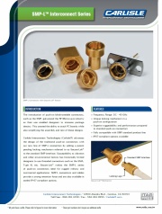
    Carlisle Interconnect Technologies advances the design of the traditional push-on connectors with the new line of SMP-L connectors, which add a patent pending locking mechanism referred to as Secure-Lok™ to the standard SMP interface.

    Three images of SMP-L Connectors, including various female connectors, a male connector, and a diagram of the locking mechanism in action.

    Features

    • Frequency Range: DC - 40 GHz
    • Unique locking mechanism in a push-on configuration
    • Superior ruggedablitiy & performance compared to standard push-on connectors
    • Fully compatible with SMP standard product line
    • IP67-compliant options available
    About two decades ago, the introduction of push-on blindmateable connectors, such as the SMP, galvanized the RF & Microwave industry as their use enabled designers to increase package density by enabling stacking of PC boards, and also simplification in assembly and test of their designs.

    This new line of push-on connectors are ideal for rugged military and commercial applications, where susceptibility to vibration and other environmental factors has historically limited designers to use threaded connectors such as the SMA, Type N, etc. SMP-L connectors and cables provide a strong retention force, and are also available in a sealed IP-67 compliant option

    ParameterSpecification
    Impedance50 Ω
    Frequency rangeDC – 40 GHz
    VSWR1.5 : 1 (DC– 40 GHz)
    Insertion Loss.06 X √f GHz
    DWV @ sea level1500 Vrms
    Insulation Resistance1000 MΩ min
    RF High Pot. @ 5MHz:1000 Vrms
    Corona Level @ 70,000’375 Vrms
    Inner Conductor Resistance6.0 mΩ
    RF Leakage-70 dB
    Force to Engage 
    Full Detent2.0 lbs
    Smooth Bore1.5 lbs
    Force to Disengage 
    Full Detent4.5 lbs
    Smooth Bore1.0 lbs
    Coupling Nut Retention Force 
    Radial MisalignmentN/A
    Axial MisalignmentN/A
    Temperature range-55˚C to +165˚C
    Environmental 
    Thermal ShockMIL-STD-202, Method 107, Cond B
    Moisture ResistanceMIL-STD-202, Method 106, except step 7b
    CorrosionMIL-STD-202. Method 101, Cond B
    VibrationMIL-STD-202, Method 204, Cond D
    ShockMIL-STD-202, Method 213, Cond I
    MetalSpecification
    BeCu (Beryllium Copper)ASTM B 196 and/or ASTM B 197
    BrassASTM B 36, B121, B16, B16M
    Stainless SteelASTM A484/ A582 or A555/581
    Iron-Nickel-CobaltASTM F-15
    DielectricSpecification
    Virgin PTFE FluorocarbonASTM D 1710 and ASTM D 1457
    Polyamide-ImideASTM D5204 Group 2 Class 1
    GlassCorning 7070 or Equivalent
    FinishSpecification
    Gold (75u in. Typ.)ASTM-B488 Type 1, Class 1.25
    Nickel (100u in. Typ.)SAE AMS-QQ-N-290
    PasivationASTM A967