
-


-
產品搜尋
首頁 > Power/Data-Cable(進口電線電纜)> Fireproof-Fire Resistant LSOH Sheathed Cables(FIREFLEX) 耐火級低煙無毒電纜線 > CALEDONIAN-Fire Resistant Fire Alarm Cables (950°C 180 minutes)耐火級低煙無毒火警警報電纜線
耐火級低煙無毒火警警報電纜線")


5543587
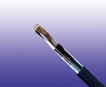
商品編號: CALEDONIAN-JE
CALEDONIAN-Fire Resistant 225V SR Insulated & LSZH Sheathed Fire Alarm Cables (950°C 180 minutes)耐火級低煙無毒火警警報電纜線APPLICATION
The cables are used for the internal wiring of building when the circuit integrity during fire is
paramount. The cables are intended for use in fire fighting plants with special ceramized silicone
insulation, with and without aluminum foil and LSZH outer sheath. The fire alarm cables with 30 to 90
minutes circuit integrity should be used for control voltages and data transfer in alarm and fire alarm
systems, where a system circuit integrity E30/E60/E90 depending on lay system in accordance with
DIN 4102-12 is required. The circuit integrity is guaranteed with a test voltage of 110V.
STANDARDS
Basic design to VDE 0815玉山 / 台新 / 華南 / 萬泰 / 兆豐 / 遠東 / 新光 / 永豐 / 第一 / 彰化 / 合庫 / 日盛 / 匯豐 / 渣打國泰世華 / 台北富邦 / 大眾銀行 / 台灣中小企銀/台中商銀 / 澳盛銀行


★★★★商品說明★★★★ PRODUCTS
Fire Resistant Fire Alarm Cables
225V SR Insulated & LSZH Sheathed Fire Alarm Cables
JE-H(St)H…Bd FE180 E30 (CU/SR/OSCR/LSZH 225V Class 1)
JE-H(St)HSWAH…Bd FE180 E30 (CU/SR/OSCR/LSZH/SWA/LSZH 225V Class 1)
APPLICATION
The cables are used for the internal wiring of building when the circuit integrity during fire is paramount. The cables are intended for use in fire fighting plants with special ceramized silicone insulation, with and without aluminum foil and LSZH outer sheath. The fire alarm cables with 30 to 90 minutes circuit integrity should be used for control voltages and data transfer in alarm and fire alarm systems, where a system circuit integrity E30/E60/E90 depending on lay system in accordance with DIN 4102-12 is required. The circuit integrity is guaranteed with a test voltage of 110V.
STANDARDS
Basic design to VDE 0815
FIRE PERFORMANCECircuit Integrity
IEC 60331-23; BS 6387 CWZ; DIN VDE 0472-814(FE180);
CEI 20-36/2-1; SS229-1; NBN C 30-004 (cat. F3);
NF C32-070-2.3(CR1)
System circuit integrity
DIN 4102-12, E30 depending on lay system
Flame Retardance (Single Vertical Wire Test)
EN 60332-1-2; IEC 60332-1-2; BS EN 60332-1-2;
VDE 0482-332-1 ; NBN C 30-004 (cat. F1); NF C32-070-2.1(C2);
CEI 20-35/1-2; EN 50265-2-1*; DIN VDE 0482-265-2-1*
Reduced Fire Propagation (Vertically-mounted bundled wires & cable test)
EN 60332-3-24 (cat. C); IEC 60332-3-24; BS EN 60332-3-24; VDE 0482-332-3; NBN C 30-004 (cat. F2); NF C32-070-2.2(C1); CEI 20-22/3-4; EN 50266-2-4*; DIN VDE 0482-266-2-4
Halogen Free
IEC 60754-1; EN 50267-2-1; DIN VDE 0482-267-2-1;
CEI 20-37/2-1 ; BS 6425-1*
No Corrosive Gas Emission
IEC 60754-2; EN 50267-2-2; DIN VDE 0482-267-2-2;
CEI 20-37/2-2 ; BS 6425-2*
Minimum Smoke Emission
IEC 61034-1&2; EN 61034 -1&2; DIN VDE 0482-1034-1&2;
CEI 20-37/3-1&2; EN 50268-1&2*; BS 7622-1&2*
No Toxic gases
NES 02-713; NF C 20-454
Note: Asterisk * denotes superseded standard.
CABLE CONSTRUCTION
Conductors: Solid annealed bare or tinned copper sized 0.6/0.8/0.9mm as per class 1 of VDE 0295/IEC 60228.
Insulation: Silicone Rubber compound as per DIN VDE 0266.
Cabling Elements: Insulated cores are twisted to form pairs with varying lay length to minimize crosstalk. Two-pair cable had four cores laid in quad formation.
Cabling: Pairs are cabled together.In cables with 8 pairs or more, 4 pairs are assembled to form a bunch, and the bunches are then cabled together.
Cable Core Assembly: The twisted pairs are stranded to the core in layers.
Core Wrapping: One or more non hygroscopic polyester tapes are helically or longitudinally laid with an overlap prior to sheathing.
Screen: A laminated Aluminum/Polyester tape is placed in contact with solid copper 0.6mm or 0.8mm drain wire.
Inner Sheath(optional): PE or thermoplastic LSZH compound type.
Armour (optional): Either corrugated steel tape armour or galvanized steel wire is applied over an inner polyethylene sheath. For steel tape armour, the 0.15mm thick steel tape is coated with a copolymer and applied with an overlap. For steel wire armour, single layer of galvanized steel wire armour is applied.
Ripcord: Nylon ripcord may be placed parallel to the cores to facilitate sheath removal.
Drain Wire: A solid tinned earth/continuity wire shall be laid longitudinally for screened cables.
Outer Sheath: Thermoplastic LSZH compound HM2 as per DIN VDE 0207-24 .
COLOUR CODE
Quad colour in each bundle:
Pair 1: Blue-Red Pair 2: Green-Yellow Pair 3: Green-Brown Pair 4: White-Black
The individual bundles are identified by a numbered helix.
TYPE CODE
JE- Fire alarm cable H Halogen free & zero halogen
Bd Unit stranding. (St) Static shield of Aluminum tape
FE180 Insulation integrity (950°C 180 minutes) E30 30 minutes system circuit integrity
STA Corrugated steel tape SWA Steel wire armour
SWB Steel wire braid
Physical AND THERMAL PROPERTIES
Temperature range during operation (fixed state): -30°C – +90°C
Temperature range during installation (mobile state): -20°C – +50°C
Minimum bending radius: 8 x Overall Diameter (unarmoured cable)
10 x Overall Diameter (armoured cables)
ELECTRICAL PROPERTIESConductor Diameter
mm
0.6
0.8
0.9
Conductor Size
mm2
0.283
0.5
0.312
Maximum Conductor Resistance @20°C
Ω/km
63
34.6
28.0
Maximum Loop Resistance @20°C
Ω/km
130
73.2
60
Minimum Insulation Resistance @500V DC @20°C
MΩ.km
100
100
100
Maximum Average Attenuation @0.8KHz
dB/km
1.7
1.2
0.74
Nominal Mutual Capacitance @0.8KHz
nF/km
120
120
120
Maximum Capacitance Unbalance K1 @0.8KHz pair-to-pair
pF/100m
200
200
200
Working Voltage
V
225
225
225
Nominal Insulation Thickness
mm
0.3
0.4
0.45
Nominal Insulated Conductor Diameter
mm
1.2
1.6
1.7
2026/6/12 下午 11:29:17


- YEIDA宜大電線有限公司
- 宜大(YEIDA) 為美國 BELDEN and ALPHA 公司 代理商 (經銷商)
- E-mail: yeida.lin@msa.hinet.net
- E-mail : yeida@ms79.hinet.net
- TEL:(02)2995-4668(代表號) FAX:(02)2278-1798
- 地址:新北市三重區重新路五段639之1號9F
網站所採用資料及圖檔皆屬各公司所有, 本公司決無侵權之意,如有造成不便,請聯絡本公司