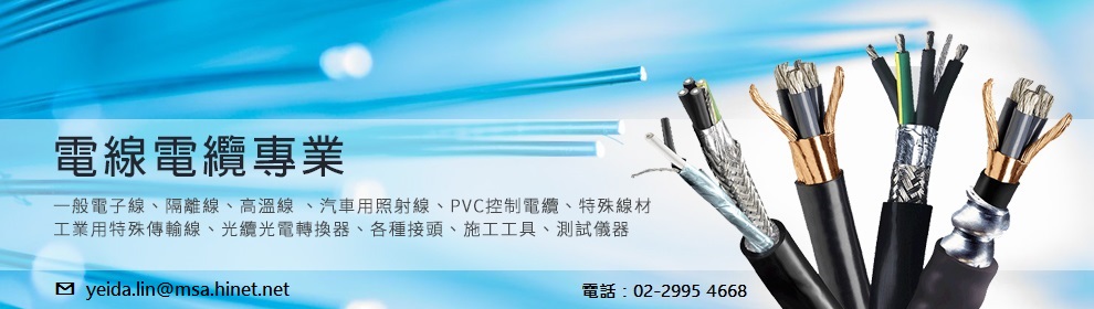
1. RFS-Parts RF 電纜 配件
    RFS-RF同軸電纜Low-Loss Foam-Dielectric Coaxial Cable
    RFS-RF洩波 電線電纜 RADIAFLEX® RAY Cable
    回上一頁
  2. 產品搜尋
    分 類:
    關鍵字:  

    首頁 > > RFS-RF洩波 電線電纜 RADIAFLEX® RAY Cable

    RFS-RAY78-50JFNA 低煙無鹵漏波電纜 7/8" RADIAFLEX® RAY Cable, A-series
    看原圖
    RFS-RAY78-50JFNA

    商品編號: RFS-RAY78-50JFNA

    RFS-RAY78-50JFNA 低煙無鹵漏波電纜 7/8" RADIAFLEX® RAY Cable, A-series


    RADIAFLEX® functions as a distributed antenna to provide communications in tunnels, mines and large
    building complexes and is the solution for any application in confined areas.
    Slots in the copper outer conductor allow a controlled portion of the internal RF energy to be radiated into
    the surrounding environment. Conversely, a signal transmitted near the cable will couple into the slots and be
    carried along the cable length.
     

    RADIAFLEX® is used for both one-way and two-way communication systems and because of its broadband
    capability, a single radiating cable can handle multiple communication systems simultaneously.
     

    This RADIAFLEX® radiating cable utilize a low-loss cellular polyethylene foam dielectric and a smooth
    copper outer conductor which offers a superior electrical performance together with good bending properties.


    Product Description

    RADIAFLEX® functions as a distributed antenna to provide communications in tunnels, mines and large building complexes and is the solution for any application in confined areas.

    Slots in the copper outer conductor allow a controlled portion of the internal RF energy to be radiated into the surrounding environment. Conversely, a signal transmitted near the cable will couple into the slots and be carried along the cable length.

    RADIAFLEX® is used for both one-way and two-way communication systems and because of its broadband capability, a single radiating cable can handle multiple communication systems simultaneously.

    This RADIAFLEX® radiating cable utilize a low-loss cellular polyethylene foam dielectric and a smooth copper outer conductor which offers a superior electrical performance together with good bending properties.

    Features/Benefits
    • Broadband from 30 MHz to 1000 MHz
    • Optimized for high frequencies and digital transmission
    • Low coupling loss variation
    • For tunnel applications

    RAY cable, A-series
    Technical Specifications
    Size [ in ] 7/8"
    Maximum Frequency [ MHz ]  1000
    Cable Type RAY
    Jacket JFN: halogen free, non corrosive, flame and fire retardant, low smoke, polyolefin
    Test methods for fire behaviour of cable :
    IEC 60754-1/-2 smoke emission: halogen free, non corrosive
    IEC 61034 low smoke
    IEC 60332-1 flame retardant
    IEC 60332-3-24 fire retardant
    Slot Design Groups of slope slots at short intervals
    Previous Model Number RAY78-50JFN
    Impedance [ Ω ] 50 +/-2
    Velocity [ % ] 89
    Capacitance [pF/m (pF/ft)] 75 (22.9)
    Inductance [ µH/m (µH/ft)] 0.1875 (0.057)
    Inner Conductor dc Resistance [ Ω/km (1000 ft) ] 1.46 (0.44)
    Outer Conductor dc Resistance [ Ω/km (1000 ft) ] 2.16 (0.66)
    Outer Conductor Material:  Overlapping Copper Foil
    Inner Conductor Material:   Copper Tube
    Diameter over Jacket [ mm (in) ] 28.5 (1.12)
    Diameter Outer Conductor: [ mm (in) ] 23.8 (0.94)
    Diameter Inner Conductor: [ mm (in) ] 9.3 (0.37)
    Minimum bending radius, single bending [ mm (in) ] 350 (13.8)
    Cable Weight [ kg/m (lb/ft) ] 0.60 (0.40)
    Max. tensile force [ N (lb) ] 2300 (507)
    Indication of Slot Alignment Bulge atop slots
    Storage temperature [ °C (°F) ] -70 to +85 (-94 to +185)
    Installation temperature [ °C (°F) ] -25 to +60 (-13 to +140)
    Operation temperature [ °C (°F) ] -40 to +85 (-40 to +185)
    Stop band [ MHz) ] 240-300, 500-590, 750-860
    Recommended / maximum clamp spacing [ m (ft) ] 0.9 (3)
    Minimum Distance to Wall [ mm (in) ] 80 (3.15)
    Length [ m (ft) ]  
    Rev. Number 2008/08/26
     
    Table of Losses

     
    Frequency, MHz Longitudinal Loss, dB/100 m (dB/100 ft) Coupling Loss 50%, dB Coupling Loss 95%, dB
    75 1,04 (0,32) 53 (57) 62 (66)
    150 1,48 (0,45) 58 (62) 69 (73)
    450 2,67 (0,81) 60 (62) 67 (69)
    870 5,41 (1,65) 54 (56) 63 (65)
    900 5,70 (1,74) 54 (56) 61 (63)
    960 6,46 (1,97) 54 (56) 60 (62)
    Standard conditions
     
    Notes

    Coupling loss as well as longitudinal attenuation of RADIAFLEX® cables are measured by the free space method according to IEC 61196-4.

    • Coupling loss values are measured with a radial (below 300 MHz) or orthogonal (above 300 MHz) orientated dipole antenna.

    • The coupling loss values given in brackets are average values of all three spatial orientations (radial, parallel and orthogonal) of dipole antenna.

    • Coupling loss values are given with a tolerance of ±5 dB and longitudinal loss values with a tolerance of ±5%.

    • In case of a conflict of operational and stop band, please contact RFS for further assistance.

    • As with any radiating cable, the performance in building or tunnel environments may deviate from figures based on free space method.